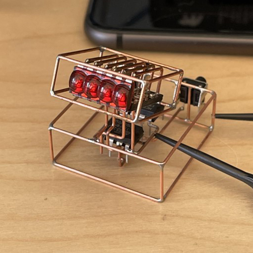
Bubbly
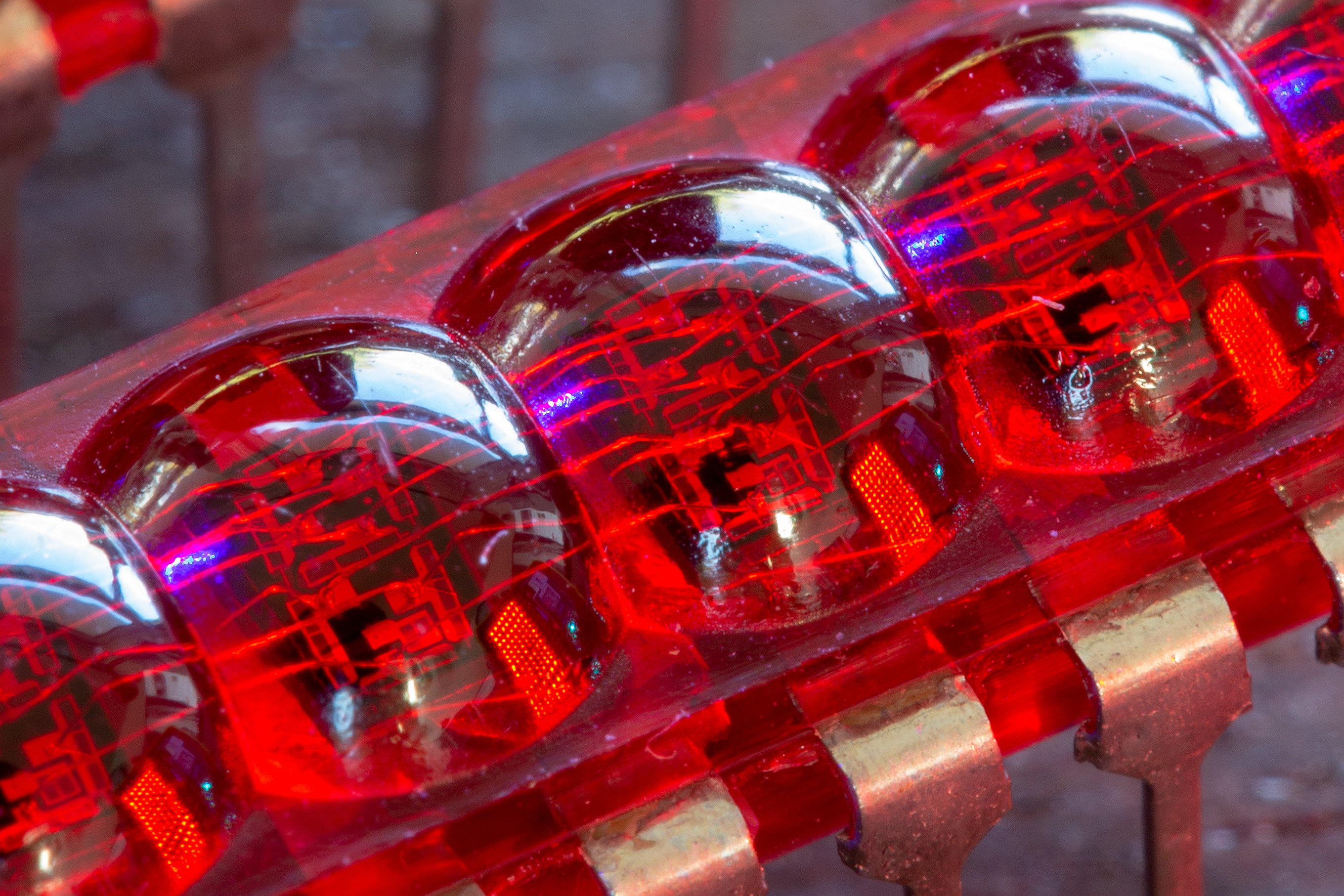
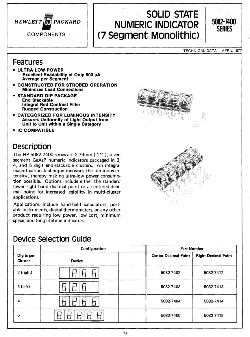
While browsing through the electronics section of the Ax-Man surplus store, I came across these beautiful vintage seven segment displays. The tiny dome lenses on them were designed to make the digit appear bigger than they were. These were made by HP back in the 70s and commonly used in calculators. I had seem them floating around on eBay and at one point on Sparkfun's website but were too expensive to purchase. ( I was able to buy 50 of them for $10!)
Here is a page from the HP's datasheet catalog from 1977. The actual partnumber of the display used here is 5082-7404.
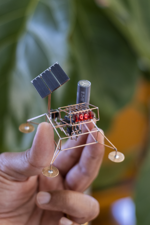
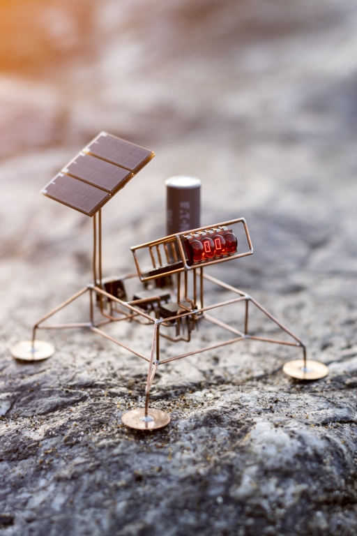
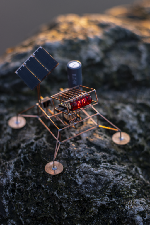
I sat on them for a few years and could not make myself to solder them on to any projects, let alone on a sculpture. But I took the plunge and that's how Bubbly was born.
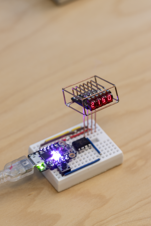
I was planning to make this little sculpture powered by a battery, but wanted to see if could make it solar power instead. I was partially successful, and the run time was only a few minutes.
Block Diagram
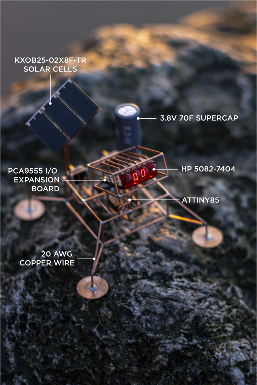
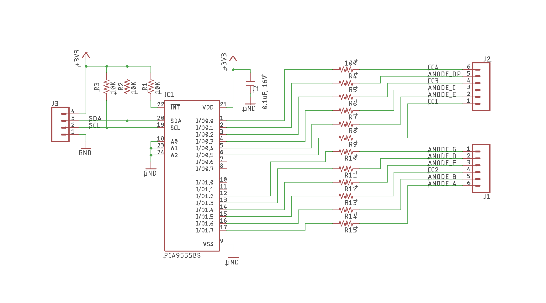
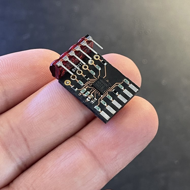
I designed a small breakout board using the PCA9555 I/O expander to drive the seven segement. This allowed me to control the display over I2C allowing me to easily integrate them in projects.
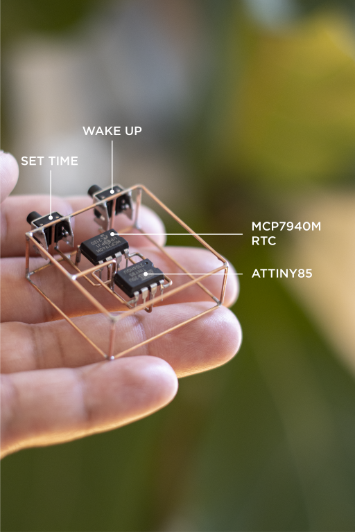
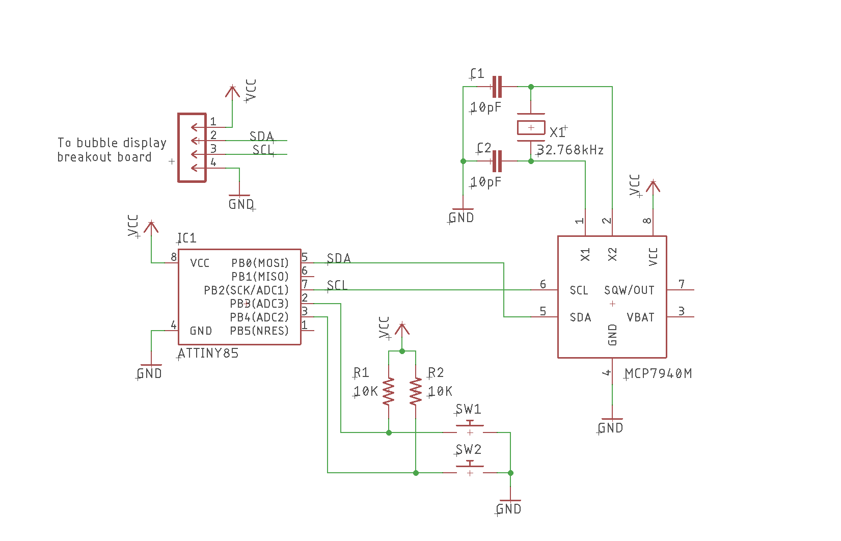
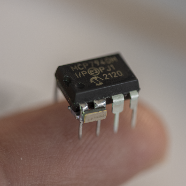
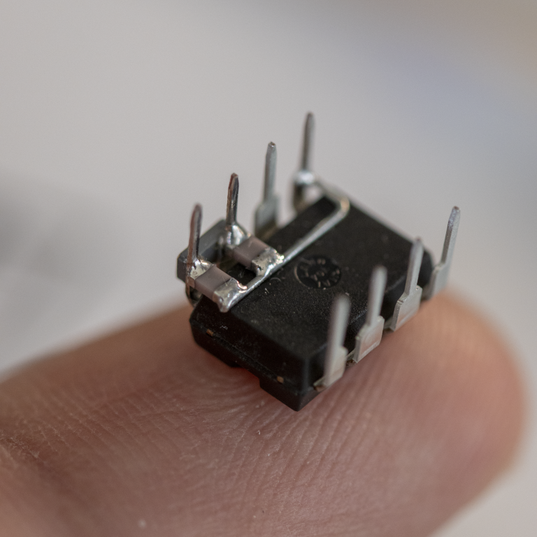
I choose the Attiny85 as the MCU to keep things simple. The MCU does not have an RTC so I had to use MCP7940M for time keeping.
Power comes from a 70F hybrid supercapacitor that is charged directly by the solarcells through a reverse blocking diode. I added a couple of push buttons to help set time and wakeup the device from sleep.
Schematic
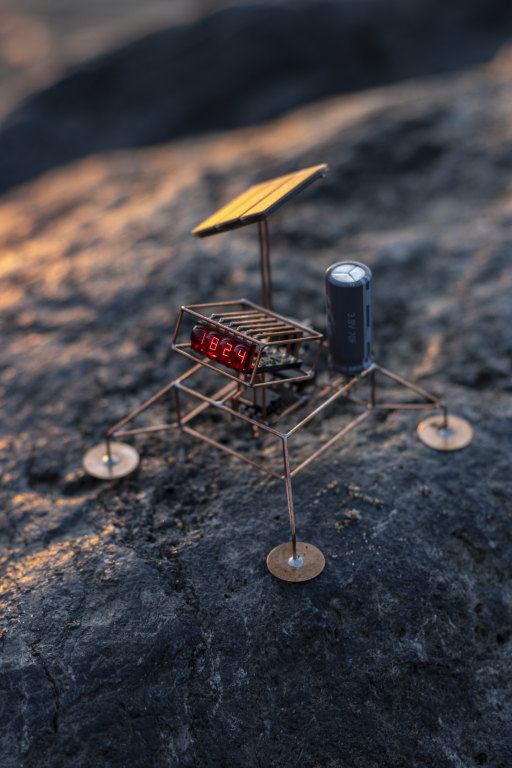
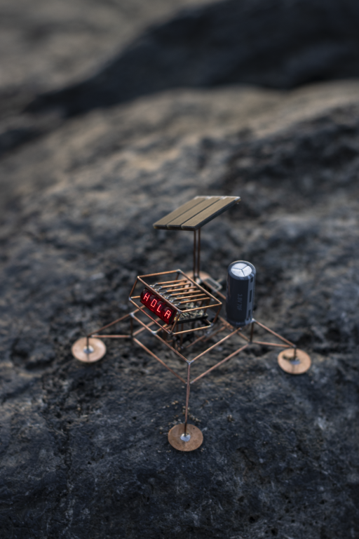
Main assembly
Bubble display breakout board based on PCA9555 I/O expander
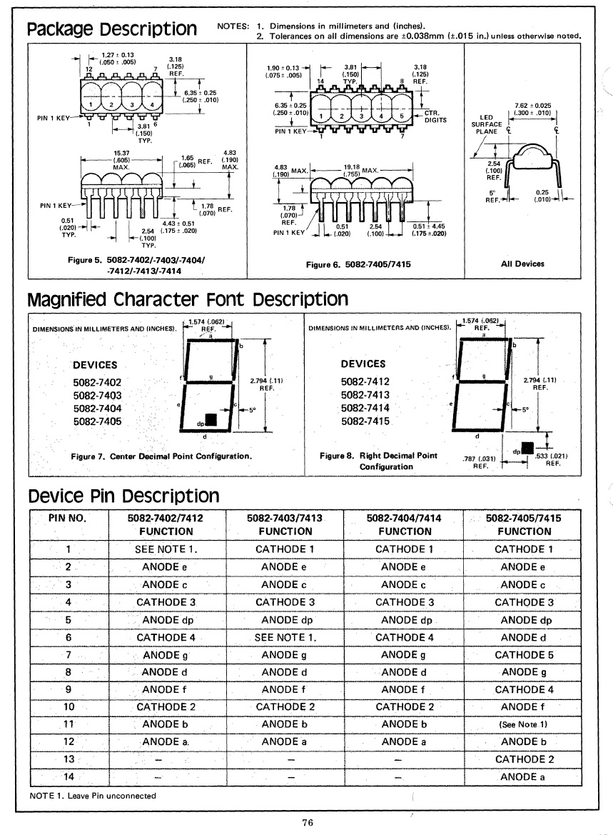
Here is the pinout of the 5082-7404 display.
Construction
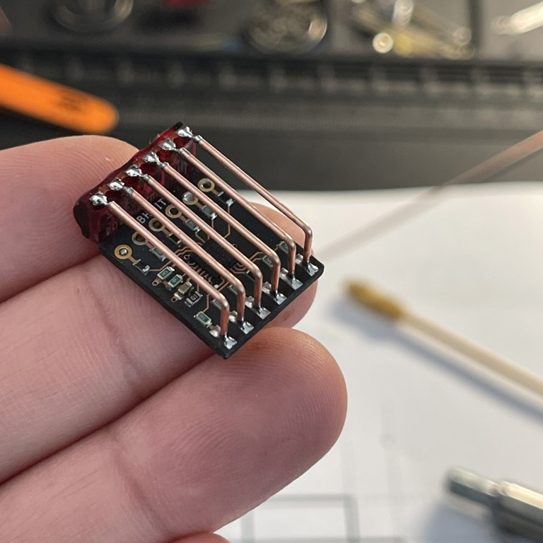
The frame and interconnects are made out of 20 AWG copper wire that was straighten into a rod.
I assembled the display board and tested it separately.
I tested out the functionality using the Adafruit's M0 Trinket and then later migrated it to ATtiny85 MCU.
RTC
I decided to solder in the crystal and load capacitors directly on the RTC chip. This helped reduce stray capacitance and (hopefully) keep the time keeping more accurate.
I then assembled the MCU+RTC using the printed PCB paper template.
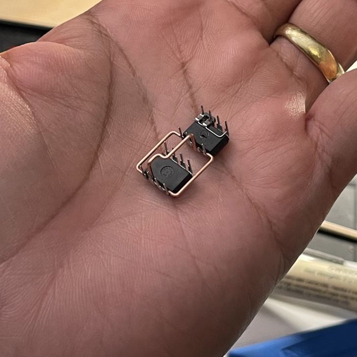
This was then soldered within a square frame that would become the lander's body.
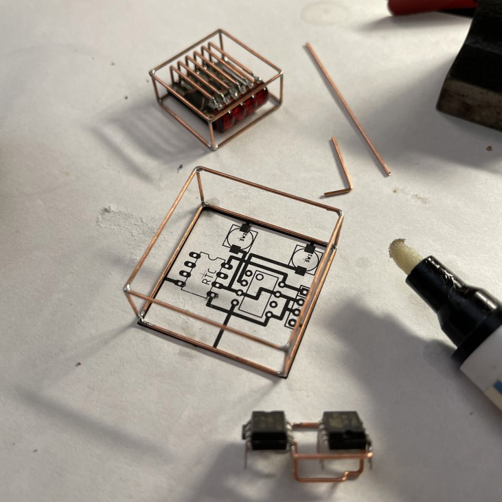
I then added the buttons, solar cell, and the super cap.
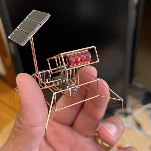
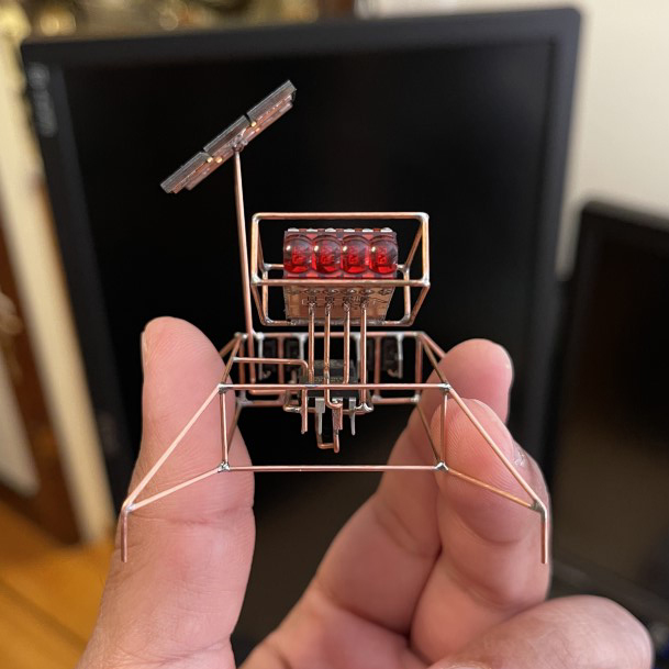
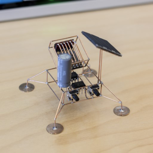
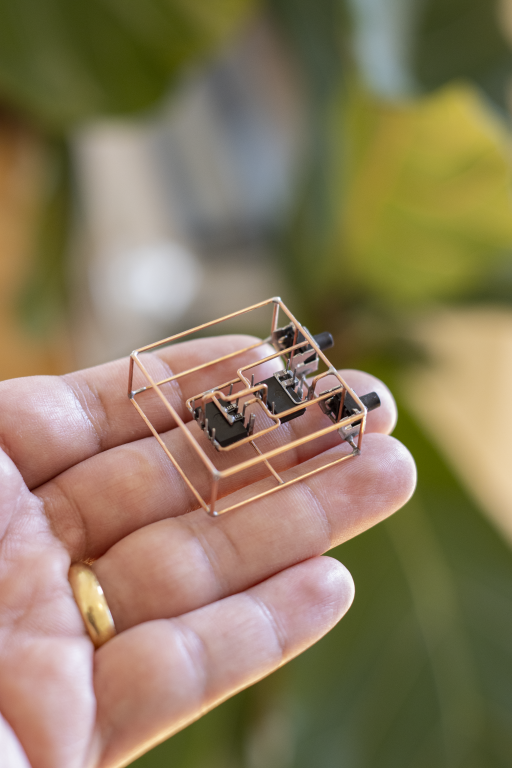
In the end I added the lander legs. The landing pads were punched out of a 0.2mm thick copper sheet.
Firmware
The complete source code is available on GitHub: https://github.com/mohitbhoite/bubbly
Libraries
You'll need to install the libraries separately within Arduino IDE.
- MCP7940.h (RTC())
- TinyWireM.h (I2C on ATtiny)
Key Setup Notes
- Use ATTinyCore in the Arduino IDE.
- Select board: ATtiny25/45/85 (No bootloader).
- Configure the clock: 8 MHz (internal).
Gallery