Attiny861 Temp Lander

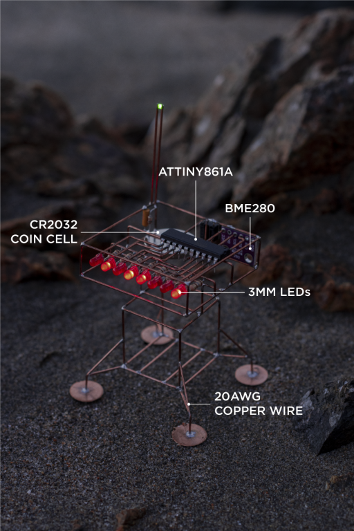
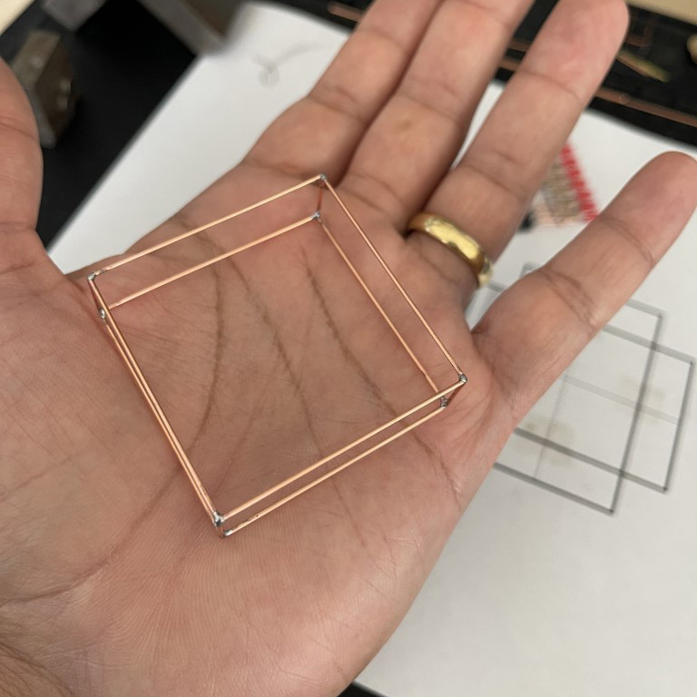
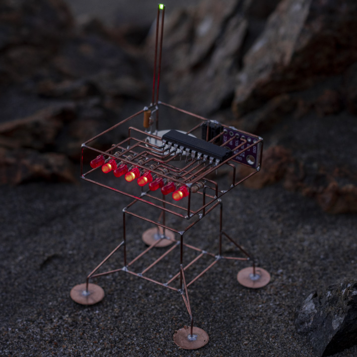
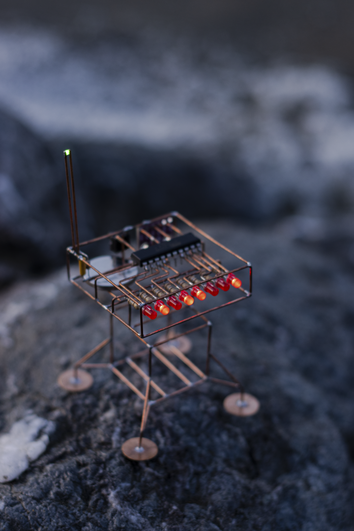
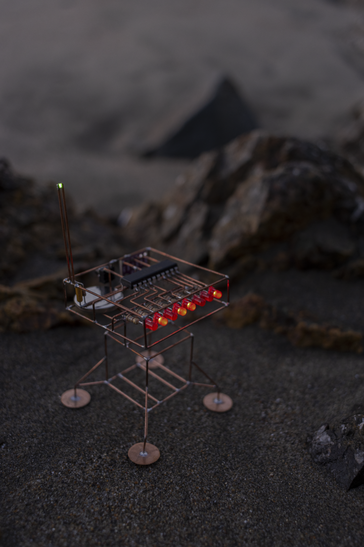
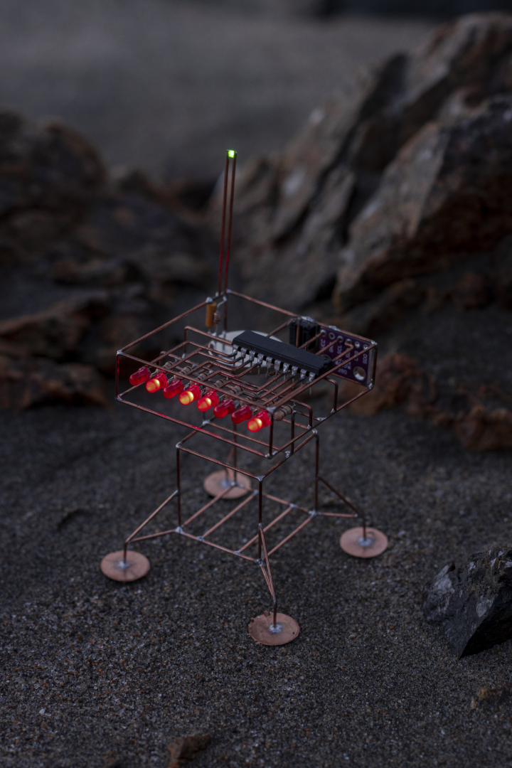
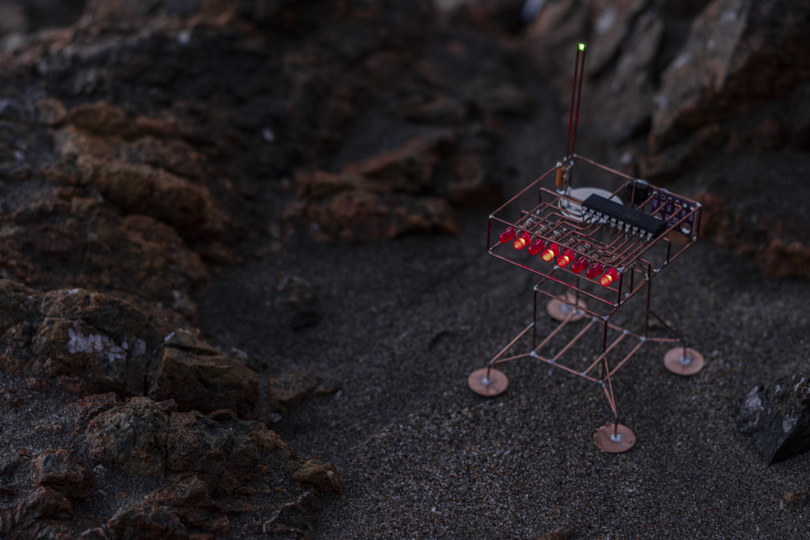
I wanted to further explore the idea of using an 8-LED array in a sculpture. In my previous build, I used an ATtiny85 + 74HC595 combo to drive the LEDs and run simple animations. This time, I switched to an ATtiny861, which allowed me to drive the LEDs directly. Along with basic animations, the sculpture can now display temperature in BCD format using a BME280 sensor. It’s powered by a CR2032 coin cell, and for this build, I used 20AWG copper instead of brass. It began as a simple box frame but evolved into a lander with added legs and a central body.
The cover photo was taken at dusk on China Beach in San Francisco, during a particularly low tide. At that time of day, the beach reveals a striking mix of black and red rocks, creating an otherworldly landscape. It made for the perfect setting to photograph the sculpture—almost like capturing it on the surface of an alien planet.
Tools
- Soldering Iron. Any good soldering iron above 60W will work. I recently started using Pinecil, and have been enjoying using it a lot. The Hakko FX888D is a solid choice as well, or a Weller.
- Solder. I have not had good luck with lead-free solder.
- Flux. I use this flux pen which is very convenient to dispense.
- Flat needle nose pliers. These flat ones are awesome, while these thin ones are good for tighter bends.
- Flush cutter. I like this one from Xuron.
- Steel wool to clean the joints.
- Printer for printing templates.
Schematic
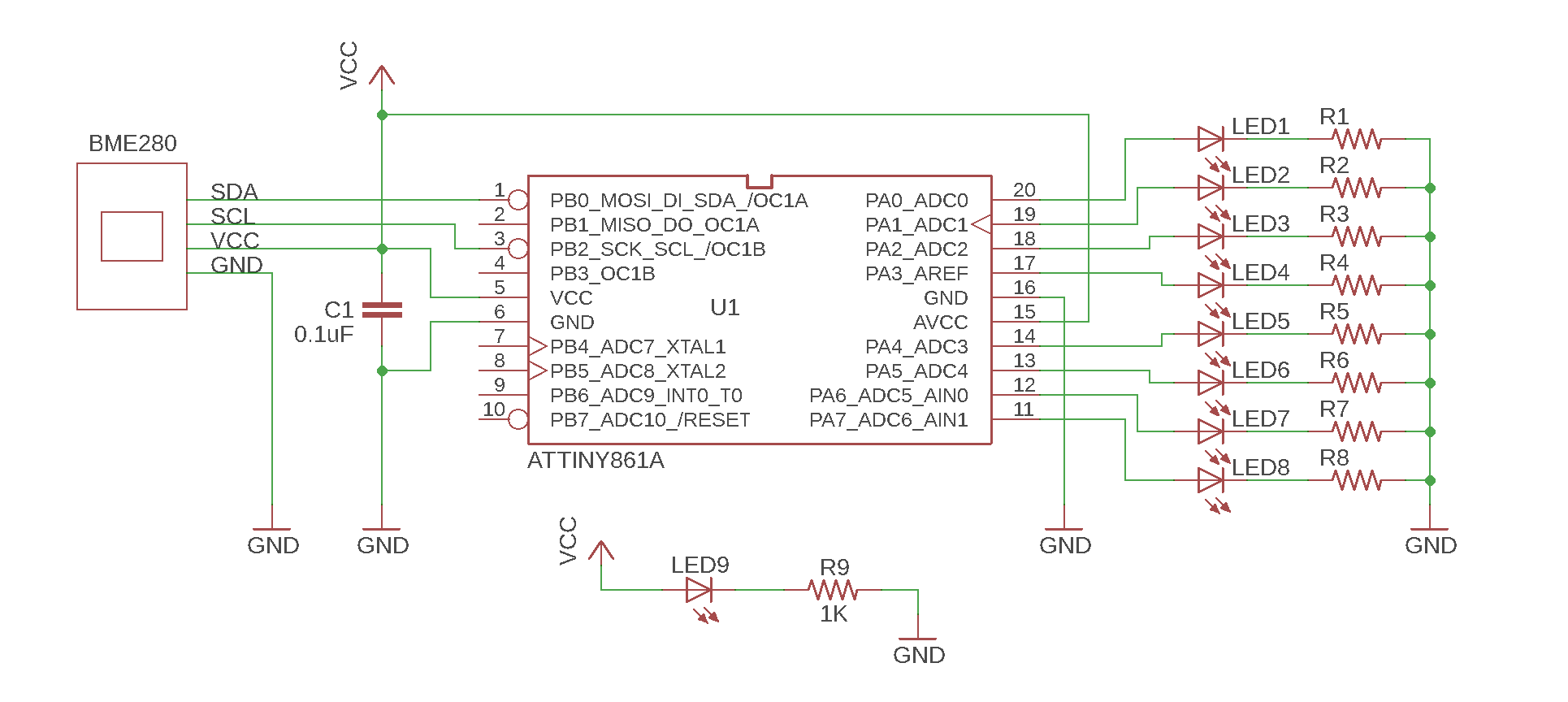
The capacitor is 0.1 µF, and the value of the current-limiting resistors depends on the LEDs you use—typically ranging from 100 Ω to 220 Ω.
Construction
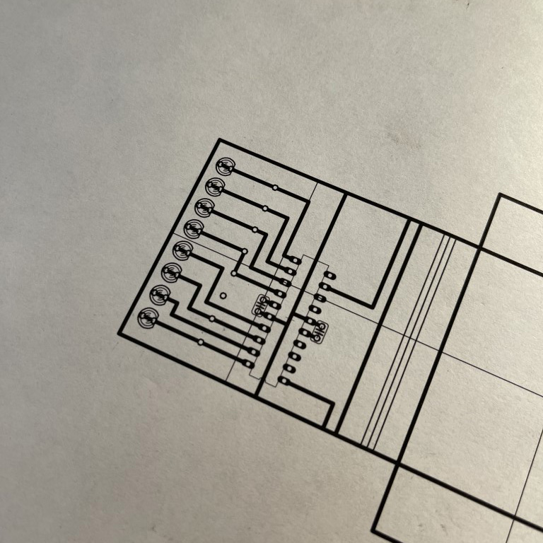
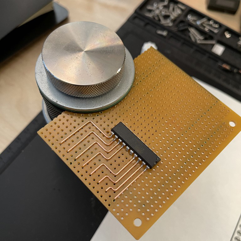
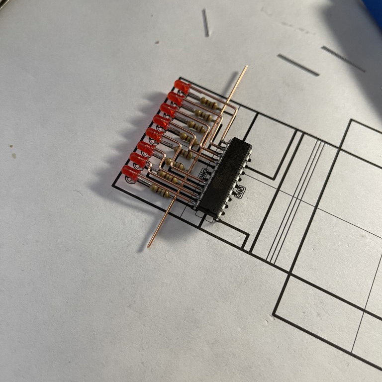
After testing the circuit on a breadboard and programming the ATtiny861 microcontroller, I created a full-scale soldering template using Autodesk Eagle. This template is essentially a 1:1 PCB layout printed on paper, used to guide the copper wire layout during assembly.
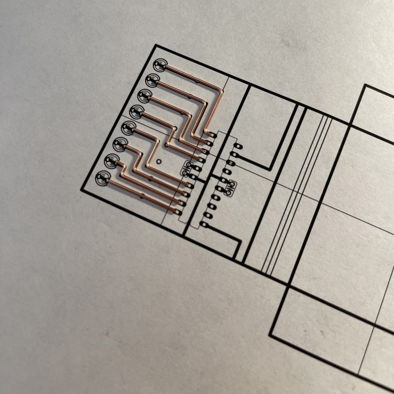
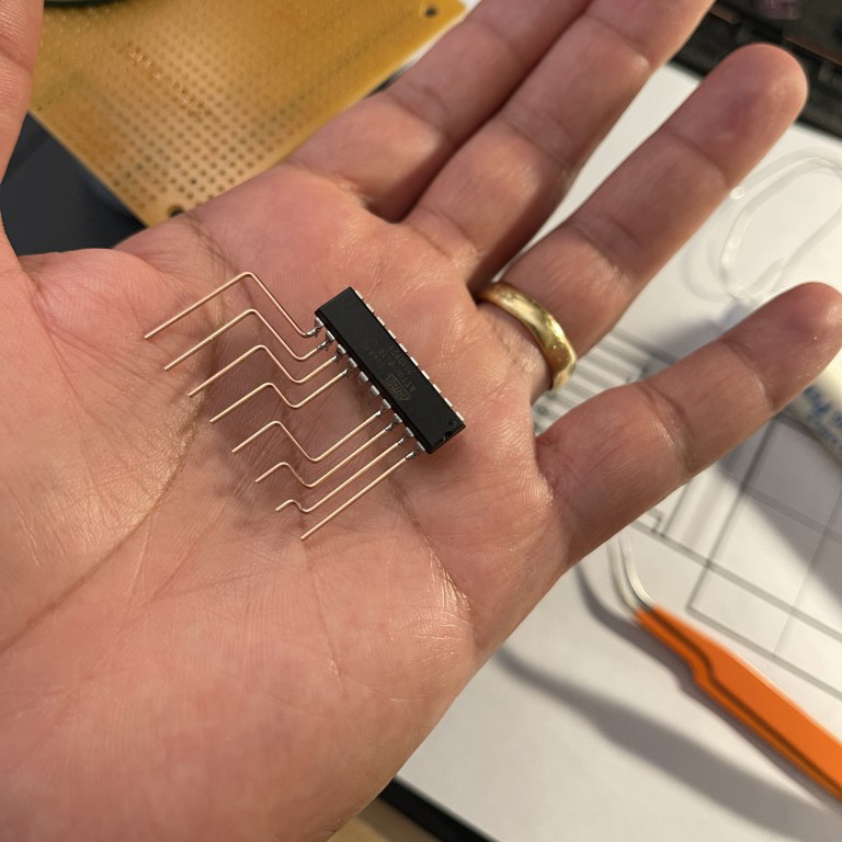
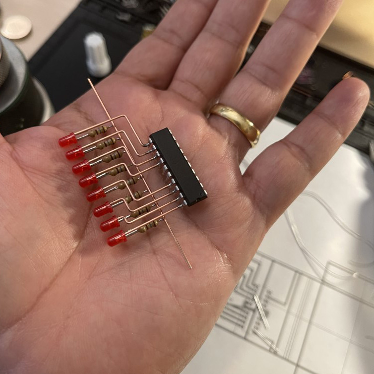
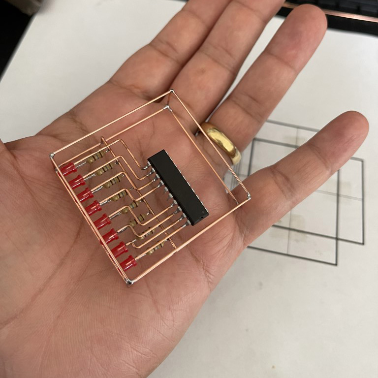
Using the printed template, I bent and cut the copper leads that connect the LEDs to the MCU. This helps maintain a clean and consistent geometry throughout the sculpture.
I often use a protoboard as a soldering guide. Its 0.1" grid spacing makes it perfect for aligning components precisely. A PCB holder helps elevate the protoboard while I solder the copper leads into place.
This technique results in crisp, evenly spaced solder joints that give the whole assembly a tidy and deliberate look.
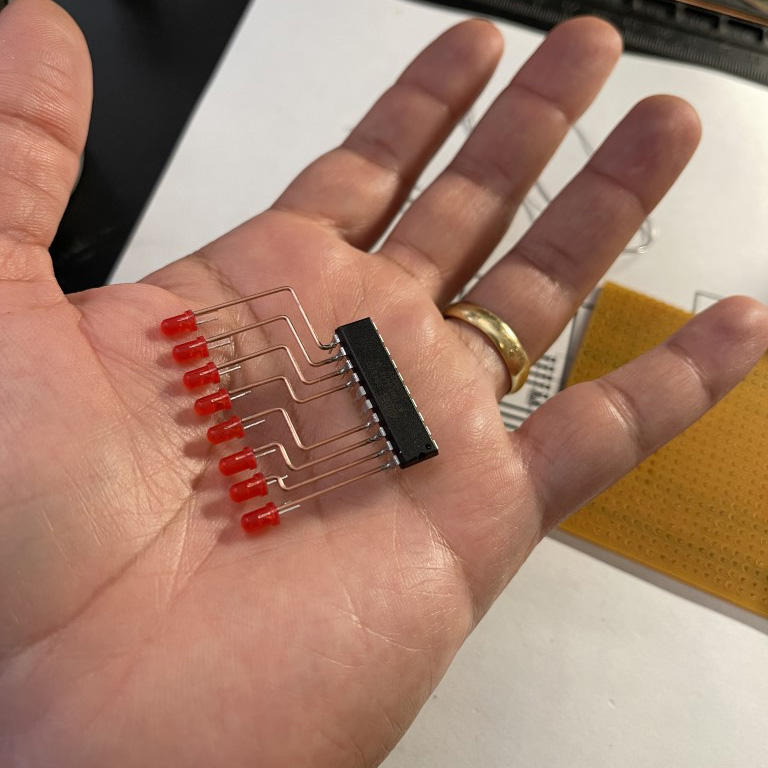
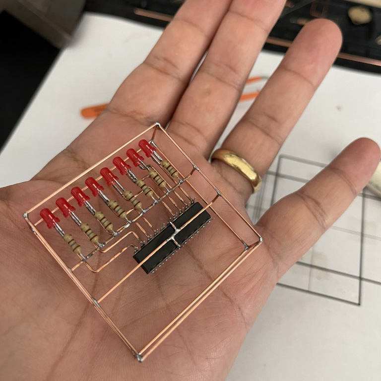
Next, I mounted the LEDs. Again, the protoboard helps align everything perfectly before committing with solder.
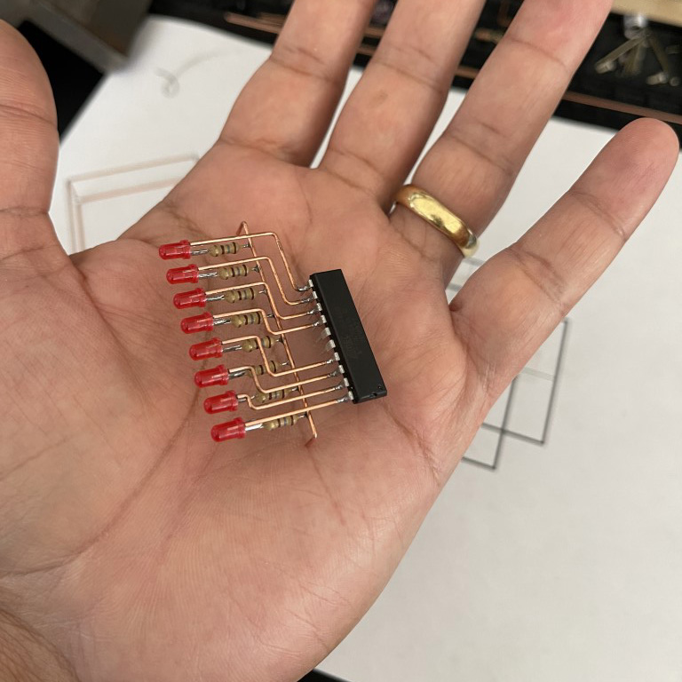
Once the LEDs were secure, I added the resistors.
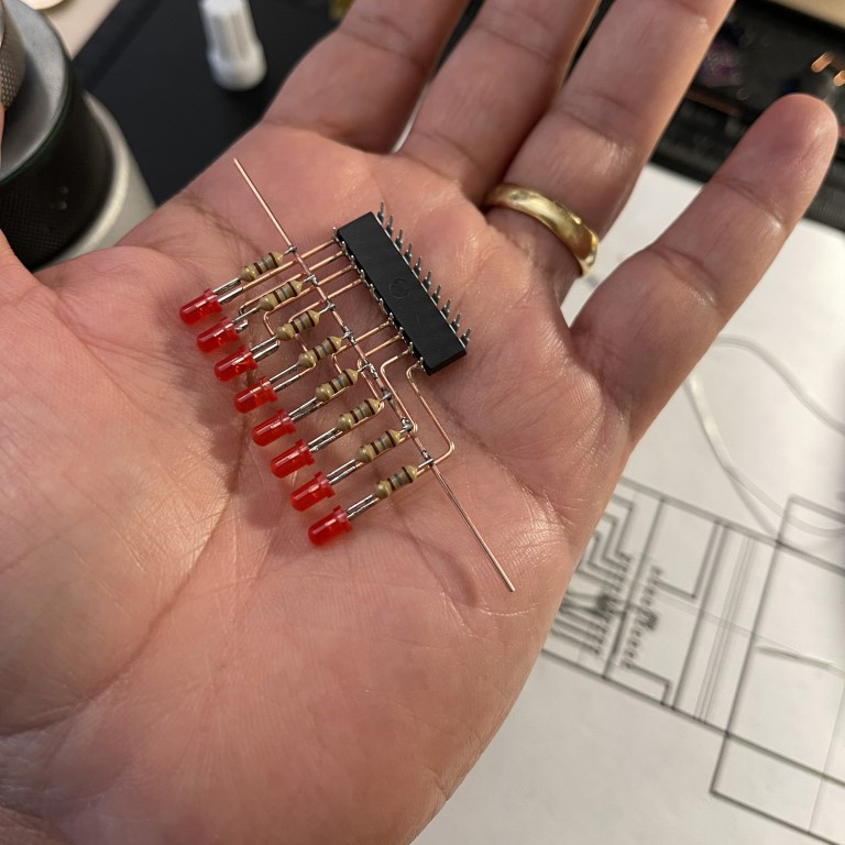
Then, I realigned everything against the original template to verify spacing, and bent the common ground bar into position.
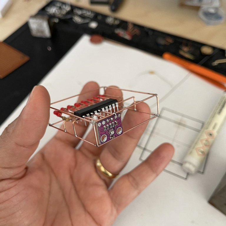
With the circuit aligned and tested, I soldered together the outer chassis and embedded the circuit within it.
Next, I soldered the BME280 temperature and humidity sensor breakout board to the frame.
Finally, I installed a small tactile switch.
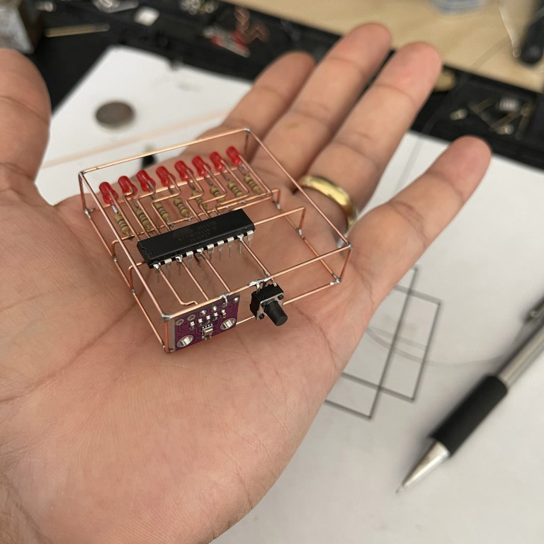
The lander legs and the power LED were added a few months later.
Firmware
I complied and loaded the firmware using Arduino IDE. For programming the ATtiny861a, I used Pololu's AVR programmer. You can also use an Arduino UNO to act as a programmer instead.
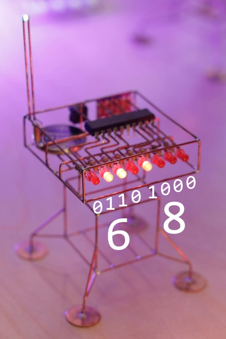
You'll need the TinyBME280 library installed if you plan to use the BME280 sensor. The temperature is displayed as a set of two 4-bit BCD numbers. For example, 68F is represented as:
06    08
0110  1000
#include <TinyBME280.h>
//
//#include <USI_TWI_Master.h>

#define BUTTON 14

byte data = 0xff;
byte button_count = 0;
byte BCDnumber = 0;

uint8_t temperature = 0;

int delay_time = 60;

void setup() {
  // put your setup code here, to run once:
  initGPIO();
  //TinyWireM.begin();
  Wire.begin();
  BME280setup();

  pattern_8();
  pattern_8();
  pattern_8();
  pattern_8();
  pattern_8();
  pattern_8();
}

//void loop()
//{
//  readTemp();
//  delay(2000);
//}

void readTemp()
{
  BME280setup();
  temperature = ((BME280temperature()/100)*1.8)+32;
  BME280sleep();
  if ((temperature <110) && (temperature > -20))
  {
     displayTemp(temperature);
  }
}

void displayTemp(uint8_t tempF)
{
  uint8_t leftNumber = tempF/10;
  leftNumber = leftNumber<<4;
  uint8_t rightNumber = tempF%10;
  uint8_t numbertoDisplay = leftNumber | rightNumber;
  setLED(numbertoDisplay);
}

void loop()
{
  if(digitalRead(BUTTON)==0)
  {
    button_count++;
    if(button_count >8) button_count = 0;
    clearLEDs();
    delay(20);
  }
  switch(button_count)
  {
    case 0:
    readTemp();
    break;
    case 1:
    pattern_1();
    break;
    case 2:
    pattern_2();
    break;
    case 3:
    pattern_3();
    break;
    case 4:
    pattern_4();
    break;
    case 5:
    pattern_5();
    break;
    case 6:
    pattern_6();
    break;
    case 7:
    pattern_7();
    break;
    case 8:
    pattern_8();
    break;
  }

}

void initGPIO(void)
{
  for(int i=0;i<8;i++)
  {
    pinMode(i,OUTPUT);
  }
  pinMode(BUTTON,INPUT_PULLUP);

  for(int i=0;i<8;i++)
  {
    digitalWrite(i,0);
  }
}

void setLED(uint8_t pattern)
{
  for(int i=0;i<8;i++)
  {
    digitalWrite(i,bitRead(pattern, i));
  }
}

void pattern_0(void)
{
  BCDnumber++;
  if(BCDnumber>255) BCDnumber = 0;
  setLED(BCDnumber);
  delay(200);
}

void pattern_1(void)
{
   setLED(0x00);
   delay(200);
   setLED(0xff);
   delay(200);
}

void pattern_2(void)
{
   setLED(0x0f);
   delay(200);
   setLED(0xf0);
   delay(200);
}

void pattern_3(void)
{
   setLED(0b01010101);
   delay(200);
   setLED(0b10101010);
   delay(200);
}

void pattern_4(void)
{
    for (int i = 0; i < 8; i++)
    {
      data = 0;
      bitSet(data,i);
      setLED(data);
      delay(delay_time);
    }
}

void pattern_5(void)
{
    for (int i = 7; i > -1; i--)
    {
      data = 0;
      bitSet(data,i);
      setLED(data);
      delay(delay_time);
    }
}

void pattern_6(void)
{
  for (int i = 0; i < 8; i++)
    {
      data = 0;
      bitSet(data,i);
      setLED(data);
      delay(delay_time);
    }
  for (int i = 7; i > -1; i--)
    {
      data = 0;
      bitSet(data,i);
      setLED(data);
      delay(delay_time);
    }
}

void pattern_7(void)
{
  setLED(0b10000001);
  delay(delay_time);
  setLED(0b01000010);
  delay(delay_time);
  setLED(0b00100100);
  delay(delay_time);
  setLED(0b00011000);
  delay(delay_time);
  setLED(0b00100100);
  delay(delay_time);
  setLED(0b01000010);
  delay(delay_time);
}

void pattern_8(void)
{
  setLED(0b00011000);
  delay(80);
  setLED(0b00100100);
  delay(80);
  setLED(0b01000010);
  delay(80);
  setLED(0b10000001);
  delay(80);
  setLED(0b00000000);
  delay(240);
}

void clearLEDs(void)
{
  setLED(0x00);
}
Help and Support
I’ve created a Discord server dedicated to Circuit Sculpture, and it’s grown to over 1,000 members! It’s the perfect place to ask questions, share your projects, or just hang out with others who love building circuit sculptures and electronics.
While I can’t respond to individual emails, posting your questions or ideas on the Discord channel is the best way to get my attention.
Join the community → https://discord.gg/f2dVMA8T
If you found this documentation useful, please consider supporting me on Patreon or buying me coffee! Thank you!