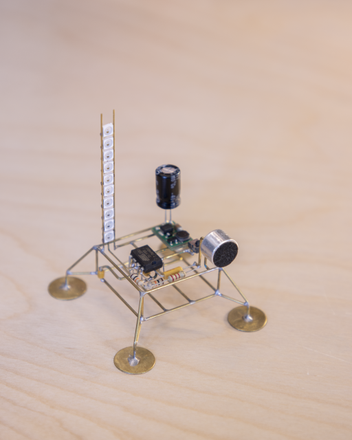
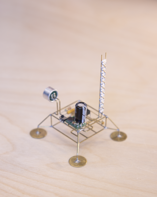
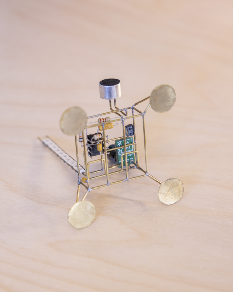
A Tiny VU Lander
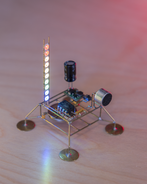
I have previously designed and build VU meter sculptures based on the classic LM3915 and the Adafruit Trinket M0 (which uses the Atmel ATSAMD21). Both of these sculptures are powered over USB. With this version, I wanted to build one in the lander form-factor that I’ve been very drawn to lately, and power it with a CR2032 coin cell.
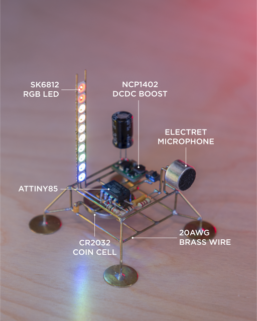
I chose to go with the ATTiny85 microcontroller and SK6812 mini (smart) RGB LEDs for this build. The SK6812 mini LEDs are smaller (3.5mm) versions of the standard (5mm) SK6812 and better than the WS2812B LEDs. These have build-in controllers (hence called “smart”), and require just a single data input which can be daisy-chained to connect multiple LEDs. Now the only caveat is that these LEDs require a minimum of 3.7V to operate, but the CR2032 is only able to provide 3V max. I observed that I can drive these LEDs successfully even down at 3.3V as long as I kept their brightness less than 40%. So in order to go from 3V to 3.3V, I added a DCDC boost convertor from Pololu (NCP1402) that can boost the voltage to 3.3V from input voltages as low as 0.8V. You can use any other boost converter that you have access to, or simply power it over USB.
The sound is fed into the ATTiny85 using an electret microphone. Traditionally one requires to amplify the microphone signal before feeding it to the ADC of the microcontroller. In this implementation, we will be using the ATtiny’s ADC in differential mode with 20x gain. This makes the circuit very simple and straightforward.
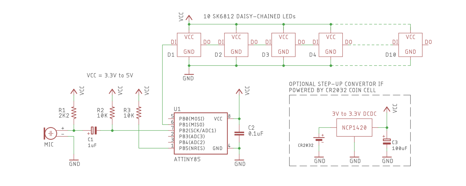
Schematic
I have repurposed the code from Adafruit’s LED Ampli-Tie project. The ATtiny85 specifics are adopted from @technoblogy’s ATtiny85 sound level meter project. My code is basically duct taped into something that works. There is plenty of room to optimize and customize it, but I’ll leave that up to you.
Remember to breadboard this circuit first before attempting to solder it together!
Firmware
The firmware is based on Adafruit’s NeoPixel examples and VU meter logic, adapted for the ATtiny85.
Complete code is available here:
attiny85-vu-meter.cpp
Key Setup Notes
- Use ATTinyCore in the Arduino IDE.
- Select board: ATtiny25/45/85 (No bootloader).
- Configure the clock: 8 MHz (internal).
#include <Adafruit_NeoPixel.h>
#include <avr/power.h>  // Required for 16 MHz Adafruit Trinket

#define N_PIXELS 10      // Number of pixels in the strand
#define MIC_PIN   A2     // Microphone pin
#define LED_PIN   0      // NeoPixel data pin

// ... Full code in the linked gist ...
Here is a video of it in action:
Support
If you found this project useful or inspiring, consider supporting me on Patreon or buying me a coffee.