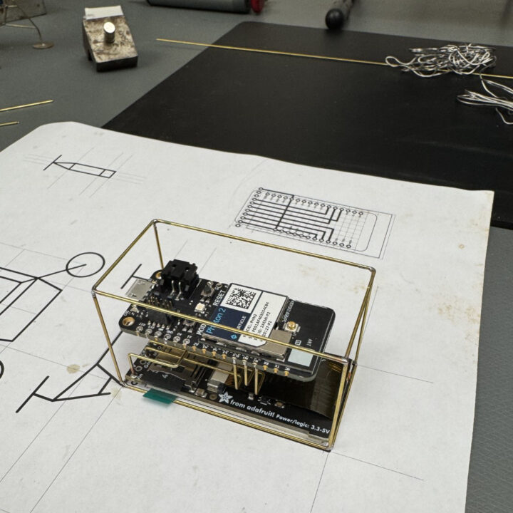
Lander R2
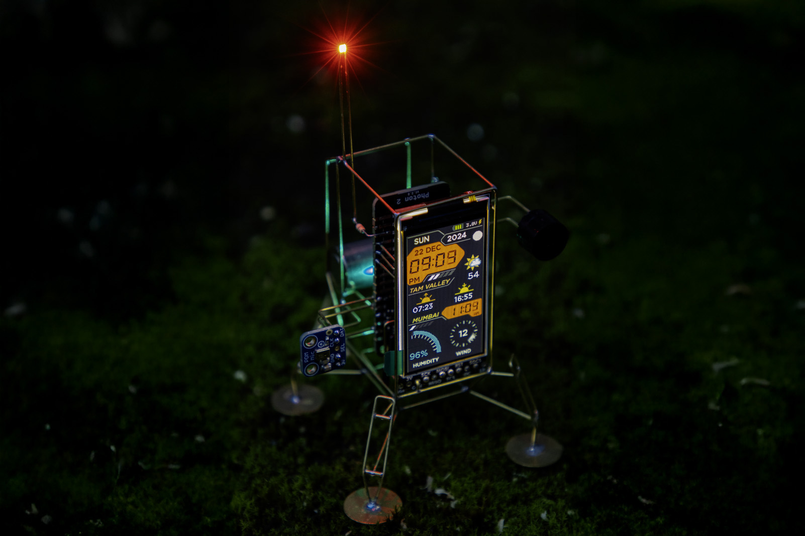
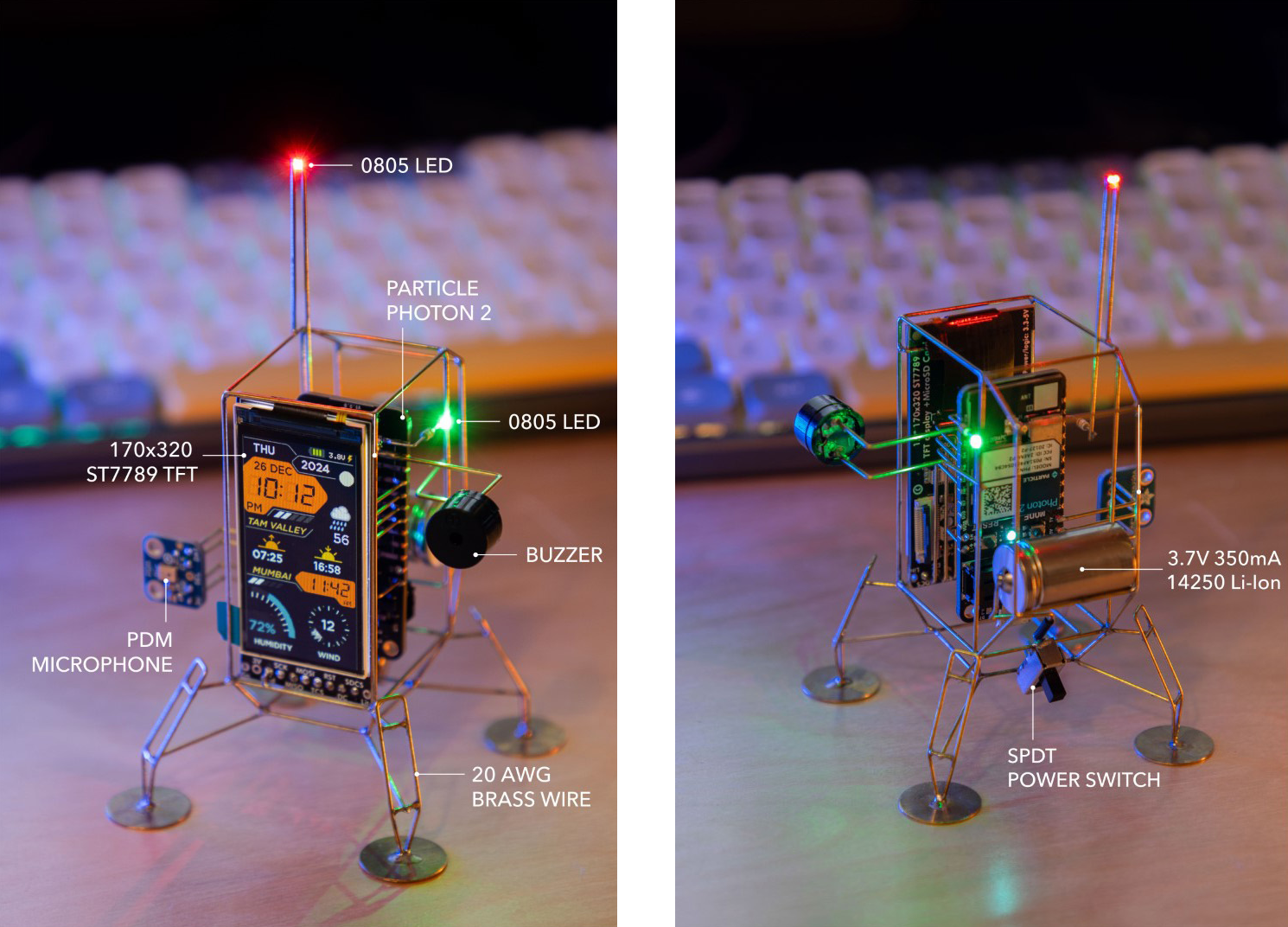
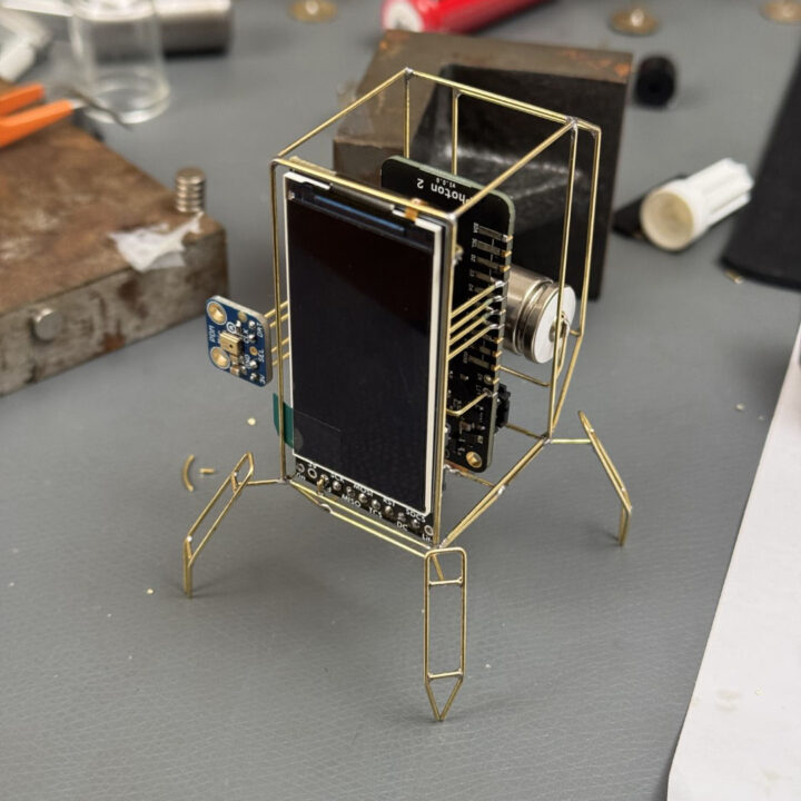
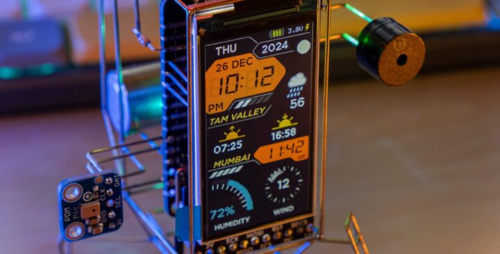
After finishing my first Photon 2 lander, I couldn’t resist building a second one—this time with more personality and functionality. The highlight of this version is a crisp, full-color 1.9″ 170×320 TFT display from Adafruit, which makes the lander feel like a tiny retro mission console.
Powered by the Particle Photon 2, this sculpture fetches local and global weather data, sunrise/sunset times, moon phases, humidity, and wind conditions, all in real time using Particle Webhooks and a handful of APIs.
To add some flair, I included a buzzer that plays polyphonic tunes and a PDM microphone for potential voice commands. While the frame design remains faithful to my previous landers, the interface has been completely reimagined—now with smooth animations, retro-inspired gauges, and a polished GUI.
Parts list
Here’s what went into this build:
- Particle Photon 2
- 1.9” 170×320 IPS TFT ST7789 display from Adafruit
- PDM Microphone (optional)
- SPDT slide switch
- 14250 Li-Ion battery
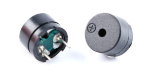
- Electromagnetic Buzzer
- 20 AWG brass or copper rods for the frame
- 14mm brass discs for the landing pads
Tools
- Soldering Iron. Any good soldering iron above 60W will work. I recently started using Pinecil, and have been enjoying using it a lot. The Hakko FX888D is a solid choice as well, or a Weller.
- Solder. I have not had good luck with lead-free solder.
- Flux. I use this flux pen which is very convenient to dispense.
- Flat needle nose pliers. These flat ones are awesome, while these thin ones are good for tighter bends.
- Flush cutter. I like this one from Xuron.
- Steel wool to clean the joints.
- Printer for printing templates.
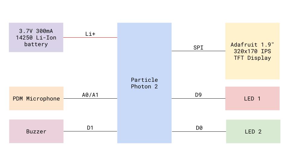
Block diagram
Controller
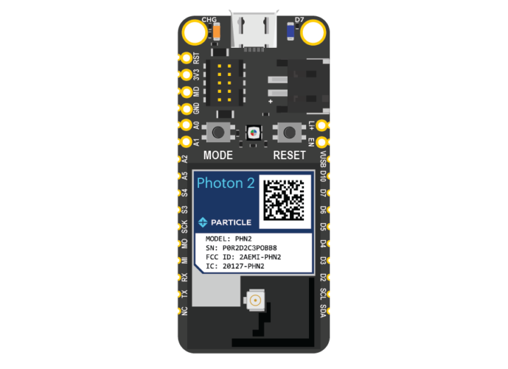
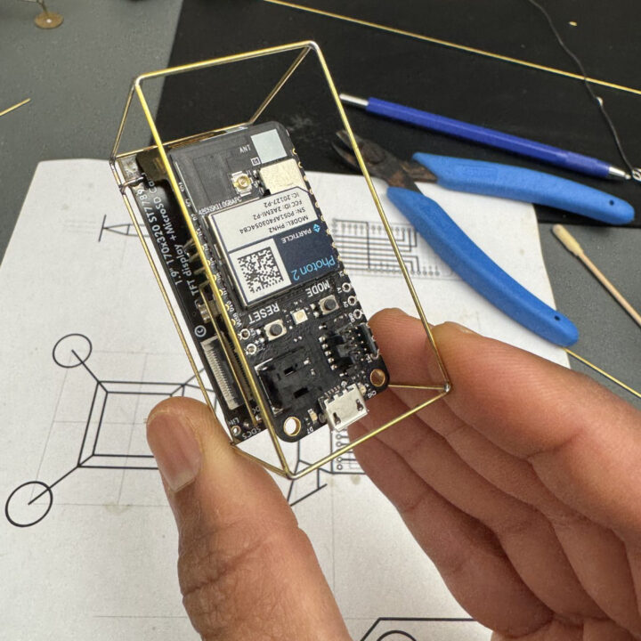
The lander is powered by the Particle Photon 2, a compact Feather-form-factor IoT board. Out of the box, it comes with Particle Device OS and seamless Wi-Fi connectivity, plus free access to the Particle Cloud (for up to 100 devices).
Under the hood:
- Realtek RTL8721 SoC with dual-band Wi-Fi and BLE 5
- ARM Cortex M33 @ 200 MHz
- 2 MB flash and 3 MB RAM
If you’ve used Arduino, ESP32, or RP2040 boards, you’ll feel right at home. You’ll just be using Particle Workbench instead of the Arduino IDE to write, compile, and upload code.
Not using a Particle board? No problem—you can adapt this project for other microcontrollers (ESP32 or RP2040 are great alternatives) with a few code tweaks.
Display
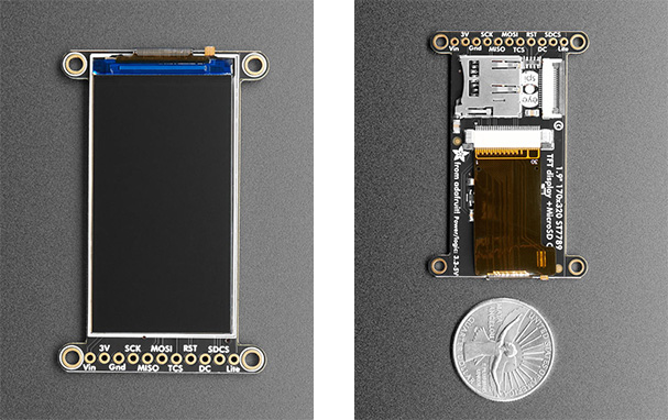
For this build, I used Adafruit’s 1.9” 170×320 IPS TFT display, which uses the ST7789 controller. It offers excellent color reproduction, wide viewing angles, and a built-in micro SD card slot—perfect for storing background graphics.
Both Adafruit’s ST7735 library and Bodmer’s TFT_eSPI work with this display, but I went with Adafruit’s library for simplicity.
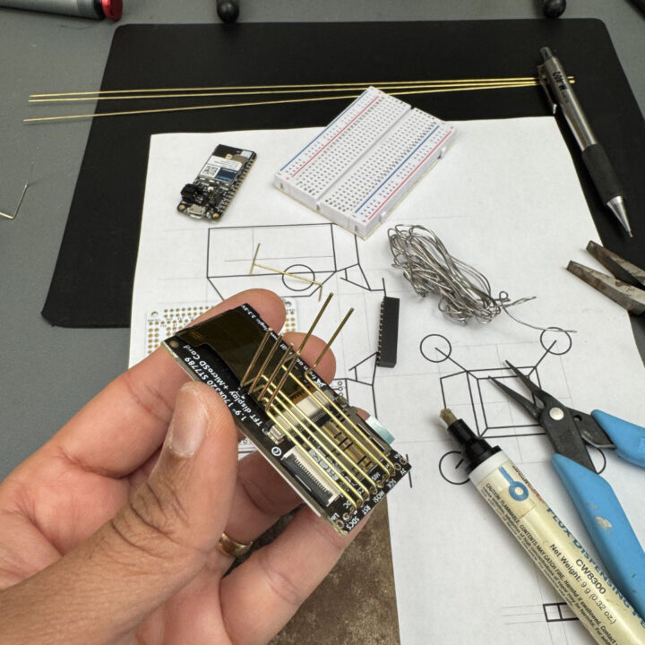
I trimmed off the four mounting hole tabs on the corners since they weren’t needed for this build and interfered with the clean frame design.
Microphone (optional)
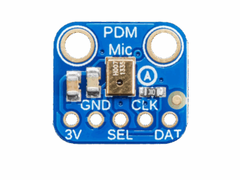
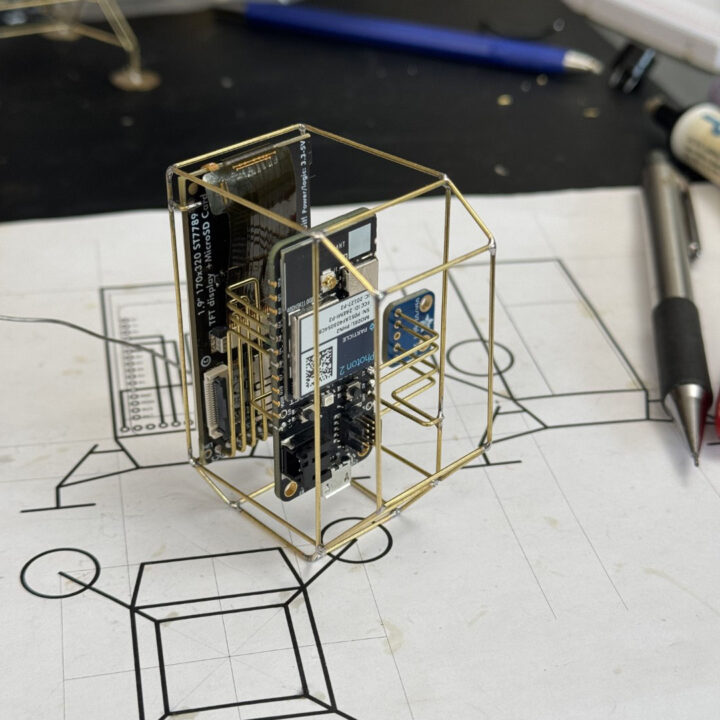
Instead of using a temperature/humidity sensor like I typically do, I opted for a PDM microphone with the idea of using it for voice commands. While the Particle Photon 2 is fully capable of this, I never got around to implementing it.
Buzzer
I’m using an electromagnetic passive buzzer to play simple tunes. I had a few on hand, so I don’t have a specific part number, but I’ve included a link to a similar one in the parts list.
Power
Please use these batteries with extreme caution as improper use will result in fire 🔥
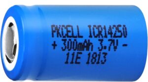
The sculpture is primarily powered by a 3.7V, 300mAh, 14250-sized (sometimes called ½ AAA) Li-Ion battery. The Photon 2 has a built-in Li-Ion battery charger, so the battery is directly connected to its +Li pin. The battery is charged simply by powering the Photon 2 over USB.
These batteries lack a protection circuit, which means an accidental short circuit could result in thermal runaway. If you’re uncomfortable working with these batteries, just power the sculpture over USB or use a LiPo battery with built-in protection like this one.
Schematic
The schematic is straightforward and doesn’t require many discrete components. The display and SD card share the same SPI bus but use different Chip Select (CS) pins. The microphone is connected to the PDM pins A0 and A1 on the Photon 2. The buzzer is directly driven by the D1 (SCL) GPIO configured as a PWM output pin.
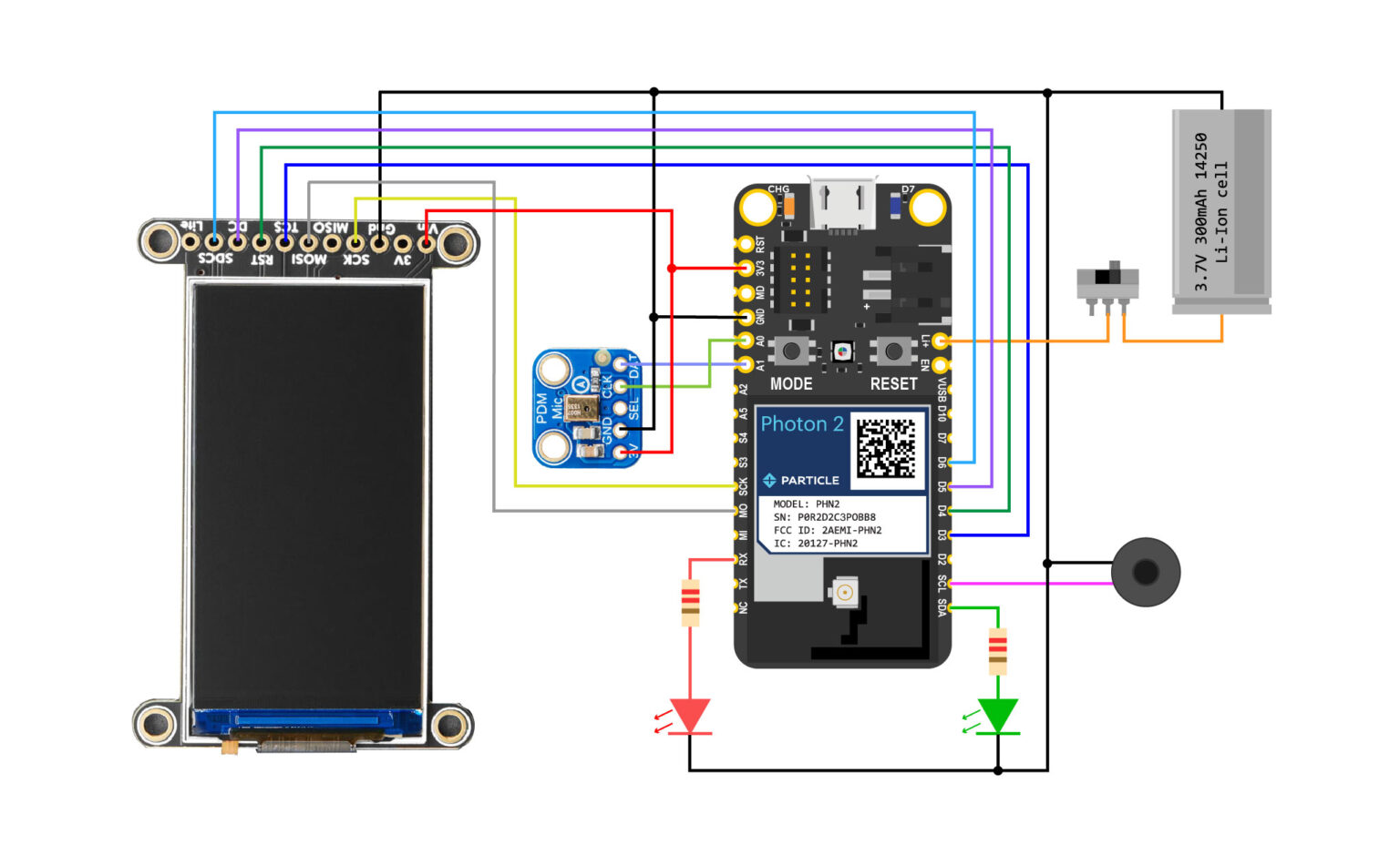
Pin Connections
| Component | Pin/Signal | Photon 2 Pin |
|---|---|---|
| Display | ||
| GND | GND | |
| VCC | 3V3 | |
| SCK | SCK | |
| MOSI | MOSI | |
| RST | D4 | |
| DC | D5 | |
| TCS (Display CS) | D3 | |
| SDCS (SD Card CS) | D6 | |
| Lite | Leave unconnected | |
| MISO | Leave unconnected | |
| PDM Mic | ||
| VIN | 3V3 | |
| GND | GND | |
| DATA | A1 | |
| CLK | A0 | |
| SEL | Leave unconnected | |
| Buzzer | ||
| Positive | D1 | |
| GND | GND | |
| Battery | ||
| + | Li+ (via switch) | |
| GND | GND | |
| LEDs (220 Ω) | ||
| Red LED | RX | |
| Green LED | D0 (SDA) |
Construction
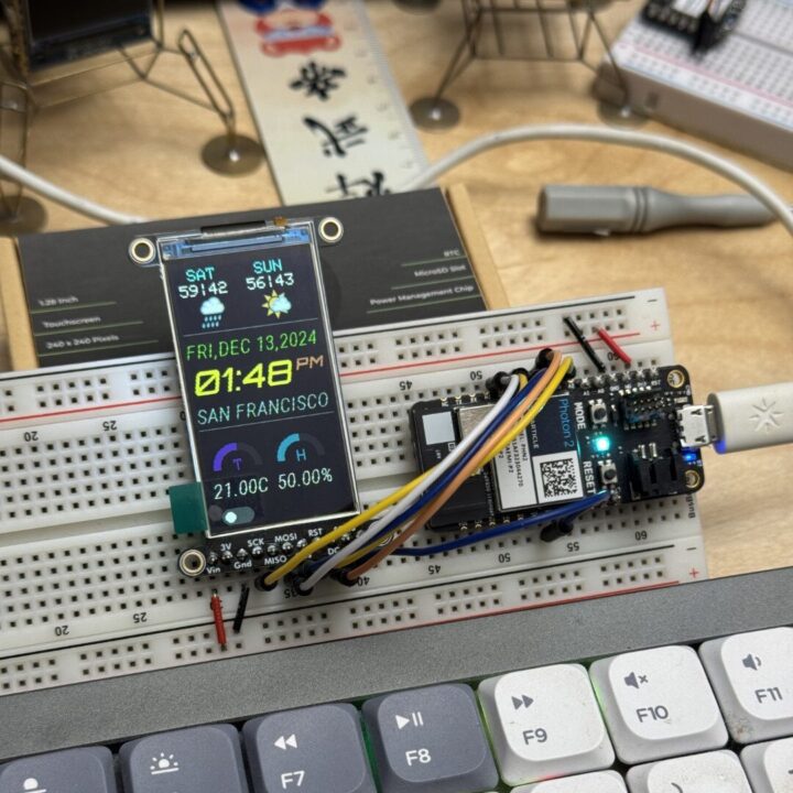
I strongly recommend that you test the code and make sure everything works as expected on the breadboarded circuit before warming up your soldering iron.
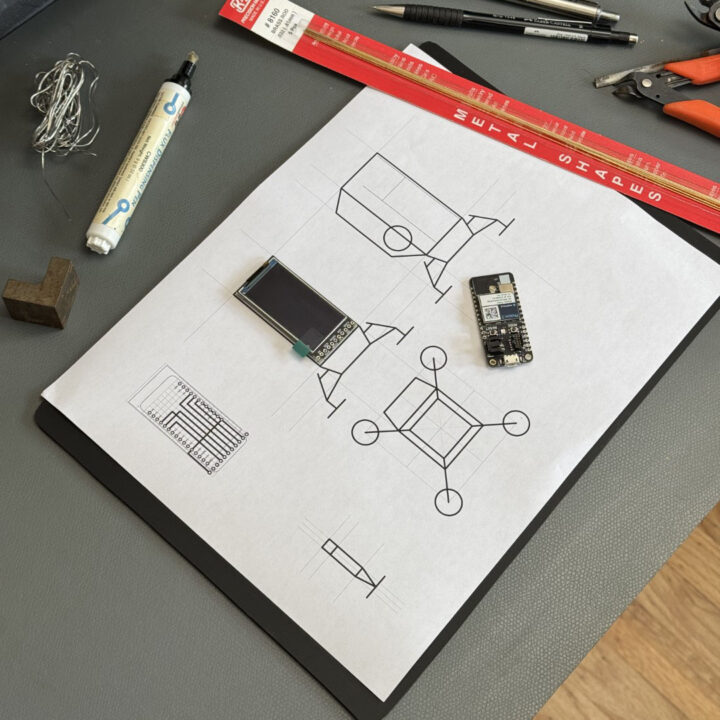
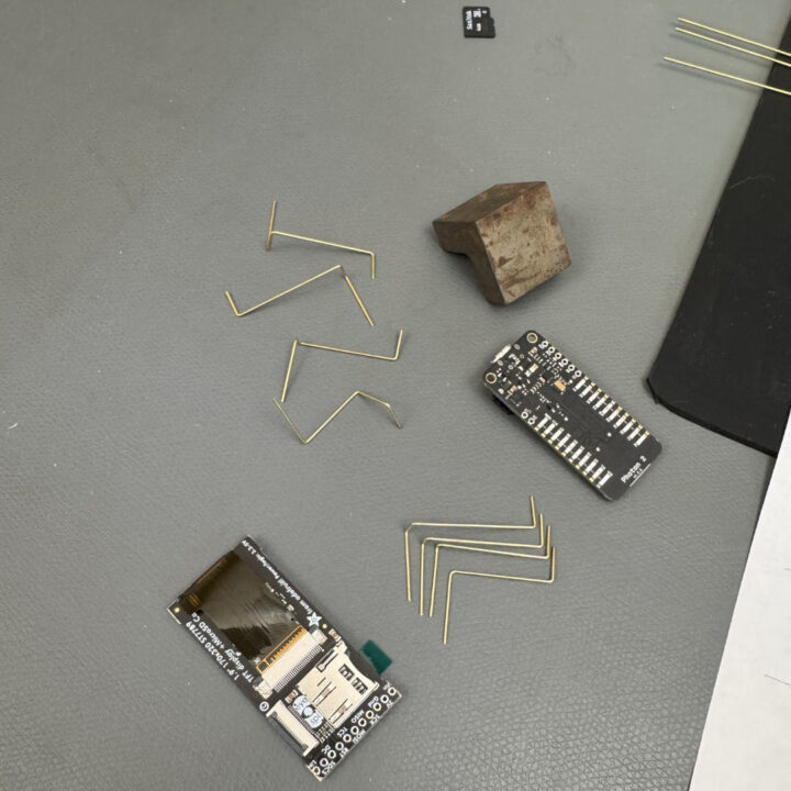
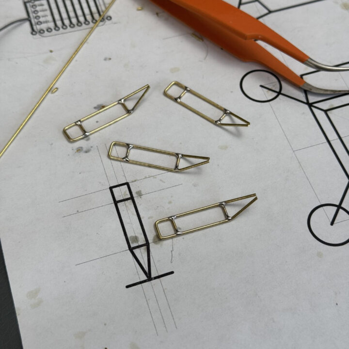
The frame is made from 20 AWG brass rods, though you can substitute copper wire of the same gauge. I made a quick video showing how to turn a brass or copper wire into a straight rod. I designed a true-to-scale template using Autodesk Eagle to guide the construction. I use flat-nose needle pliers to bend the rods and a diagonal cutter to cut them to length. The frame is connected to the GND net, which simplifies routing.
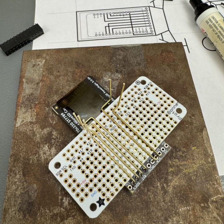
The Photon 2 ships with preinstalled headers, which I had to desolder before using it in this project. At Particle, we had custom headers made for the Photon 2 that are partially through-hole and partially SMT, which makes desoldering a bit tricky. It’s not the easiest—or most pleasant—task, but with some patience, it can be done.
I often use prototyping PCBs as makeshift solder jigs, especially when the spacing between connections is 0.1″. Very convenient!
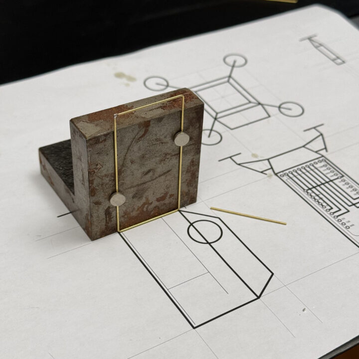
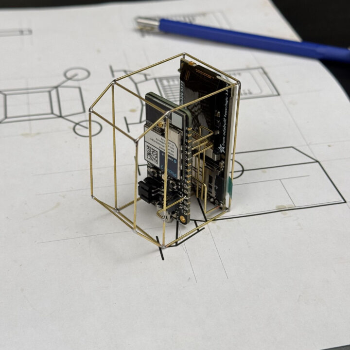
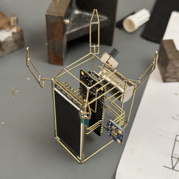
The outer “shell” was soldered with the help of an angle block and small magnets, which gives me a perfectly square frame every time.
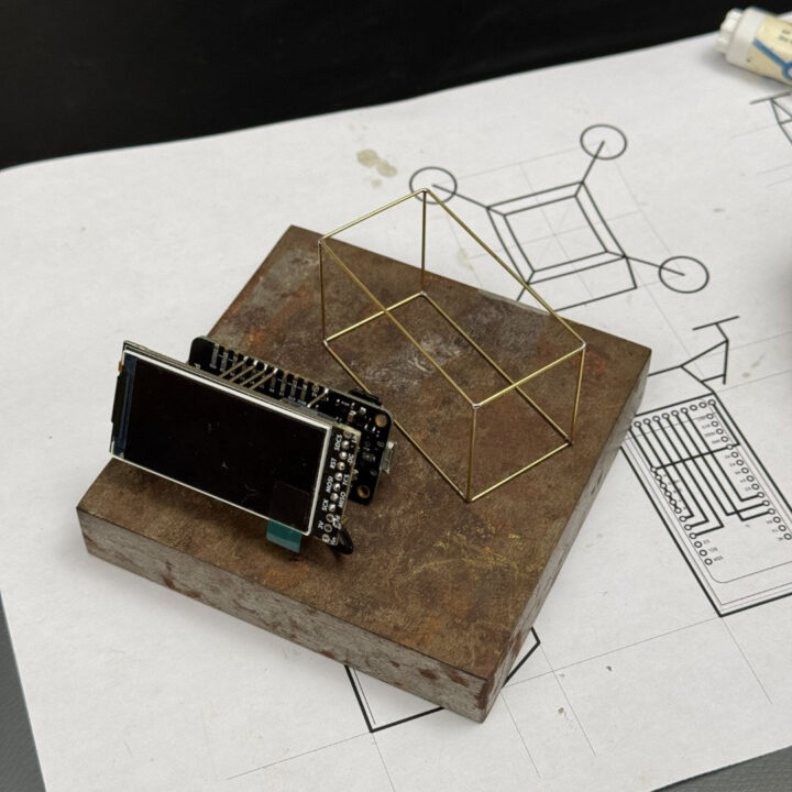
I carefully lined everything up to ensure the Photon and display assembly were properly aligned.
Since the chassis is connected to GND, I use it to secure the assembly to the outer shell.
I then added the backpack cage where I soldered in the battery.
I used the paper template to shape the lander legs. I have better photos of this step in my previous Boron Lander guide.
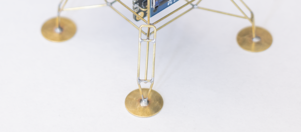
The landing pads are 14mm brass discs that I purchased from an Etsy shop. You can also make your own by punching discs out of 0.5mm thick brass or copper sheet. Remember to solder the pads at the very end of the build—if you do it earlier, you might end up with a wobbly sculpture!
Firmware
A lot of the heavy lifting in this project is handled by Adafruit’s device libraries. They’ve done an incredible job of creating open-source libraries and hardware that make projects like this much easier to build. I highly recommend supporting them by purchasing their products if you can! For this build, I’m using the Adafruit ST7735 and Adafruit GFX libraries to control the display.
The complete code for this project is available on my GitHub repository. It’s sparsely commented, but if you have questions or suggestions, feel free to open an issue or comment on the repository page. I’d be happy to help.
Designing the graphical interface
One of the most fun (and challenging) parts of this build was designing the graphical user interface (GUI) for the lander’s console. In previous projects, I’ve kept things simple—just using basic graphical primitives (boxes, lines, circles) and the default fonts from the graphics library. This time, I wanted to take it a step further and create a display that felt like a retro mission control console, complete with animations, custom fonts, and layered visuals.
This turned into a great learning experience, especially around how GUIs are designed in resource-constrained environments (like microcontrollers with limited RAM and flash memory).
Static Backgrounds: The Secret to a “Polished” Look
One of the easiest ways to make your interface look professional is by using a static background image. This background stays the same, while only certain elements (like text or gauges) are updated on top of it. This approach has several advantages:
- Instantly makes the interface look polished and adds personality.
- Rendering is much faster since you’re not redrawing the entire screen.
- Saves memory and computational power (only small screen regions need refreshing).
- Makes it easy to experiment with different color schemes and themes without touching the code.
Workflow for GUI Design
I designed several mock-up backgrounds in Adobe Illustrator (you can use Inkscape or any vector graphics tool). Illustrator lets me experiment with layout, colors, and fonts in a flexible way before committing to code.
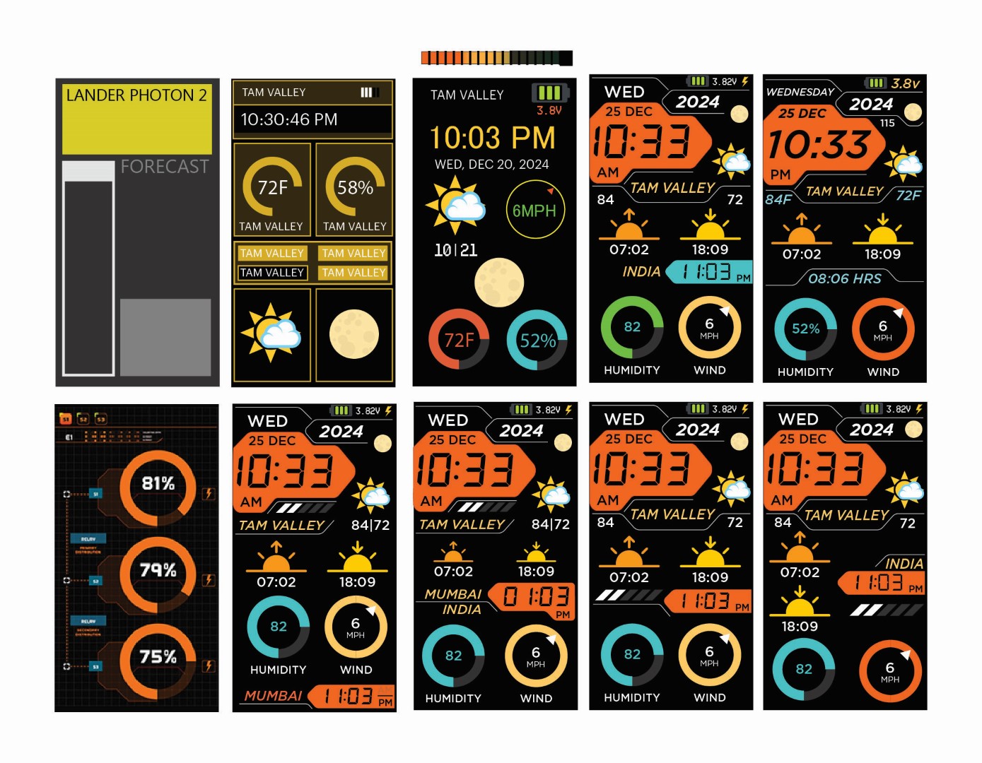
Once I was happy with the design, I exported the final static background as a .bmp file at 170×320 pixels (matching the TFT display resolution). I stored this image on the SD card.
You’ll need to edit the city names in the design to match your preferred locations.
When the device boots, the first thing it does is load this BMP onto the display. After that, I render dynamic elements—like text, gauges, and animations—on top of the background. This creates a smooth, layered effect.
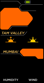
Adding Depth and Retro Vibes
A small trick I used to create a shadowed seven-segment display effect for the time readout:
- First, I render the number
88:88in a gray color as a “shadow.” - Then, I render the actual time in black, perfectly aligned on top of the shadow.
The result is a simple but effective illusion of depth, giving the display a subtle retro aesthetic.
Animations and Helper Routines
To bring the interface to life, I wrote helper routines to generate animations and draw elements like humidity and wind gauges. These routines handle small, incremental updates (rather than full-screen refreshes) to keep the interface smooth and responsive.
I also experimented with storing multiple GIFs and alternate background screens on the SD card. The main program can load and display these on-demand, allowing me to quickly swap “themes” or screens without recompiling the firmware.
Setting up Particle Webhooks
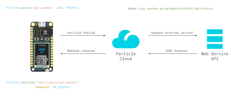
The firmware on the Photon 2 is just one piece of the puzzle when it comes to making this Lander pull data from the internet. The other key player is Particle Webhooks. A webhook acts as a bridge between your Particle device and various online services. In this project, the webhooks handle the heavy lifting—fetching and parsing weather forecasts, sunrise and sunset times, moon phases, humidity, and wind conditions, then delivering that data back to the device.
Each time the Photon 2 performs a Particle.publish, it triggers the corresponding webhook, which responds with a neatly formatted data string. The device then grabs this data by subscribing to the webhook’s response. All of this happens asynchronously in the background, so you don’t have to manage it manually—it just works!
If all of this sounds confusing or overwhelming to you, don’t worry! You can follow Particle’s documentation or join the community for support.
You’ll need to set up five webhooks for this project:
- To fetch moon phases (ipgeolocation.io)
- To fetch humidity and wind conditions (openweathermap.org)
- To fetch sunrise and sunset times (sunrise-sunset.org)
- To fetch today’s weather forecast (weather.gov)
- To fetch tonight’s weather forecast (weather.gov)
I know this is a lot, but I’ll walk you through each one step-by-step.
1. Fetch today’s moon phase
We are going to use the Astronomy API from ipgeolocation.io. They provide free (up to 1000 calls/month) API requests to retrieve simple astronomy data for a given location.
- Step 1: Create a free account on ipgeolocation.io and obtain an API key.
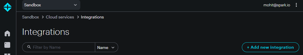
- Step 2: Go to Particle Console → Integrations → + Add New Integration.
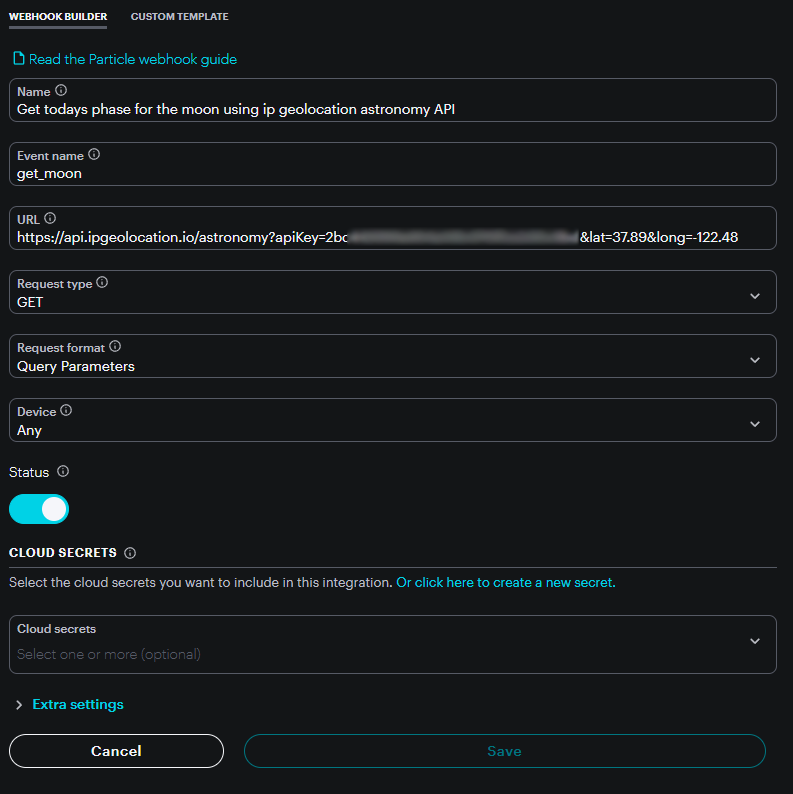
- Step 3: Scroll down and click on Custom Webhook.

- Step 4: Configure the webhook as follows. Replace
123456789with your API key and set the desired latitude and longitude:
https://api.ipgeolocation.io/astronomy?apiKey=123456789&lat=37.89&long=-122.48
- Step 5: Test your API by pasting the URL (with your key and coordinates) into your browser. You should get a JSON response like this:
{
  "location": {
    "latitude": "37.89000",
    "longitude": "-122.48000",
    "country_name": "United States",
    "state_prov": "California",
    "city": "Tiburon",
    "locality": "Tiburon",
    "elevation": "40"
  },
  "date": "2025-07-23",
  "current_time": "16:28:22.257",
  "sunrise": "06:05",
  "sunset": "20:27",
  "sun_status": "-",
  "solar_noon": "13:16",
  "day_length": "14:22",
  "sun_altitude": 44.87457579280979,
  "sun_distance": 152000449.99796304,
  "sun_azimuth": 260.3558687665176,
  "moon_phase": "NEW_MOON",
  "moonrise": "04:30",
  "moonset": "20:11",
  "moon_status": "-",
  "moon_altitude": 39.92605652468014,
  "moon_distance": 373568.3283474921,
  "moon_azimuth": 274.44385345654985,
  "moon_parallactic_angle": 61.2376803504655,
  "moon_illumination_percentage": "-0.86",
  "moon_angle": 349.34291416763665
}
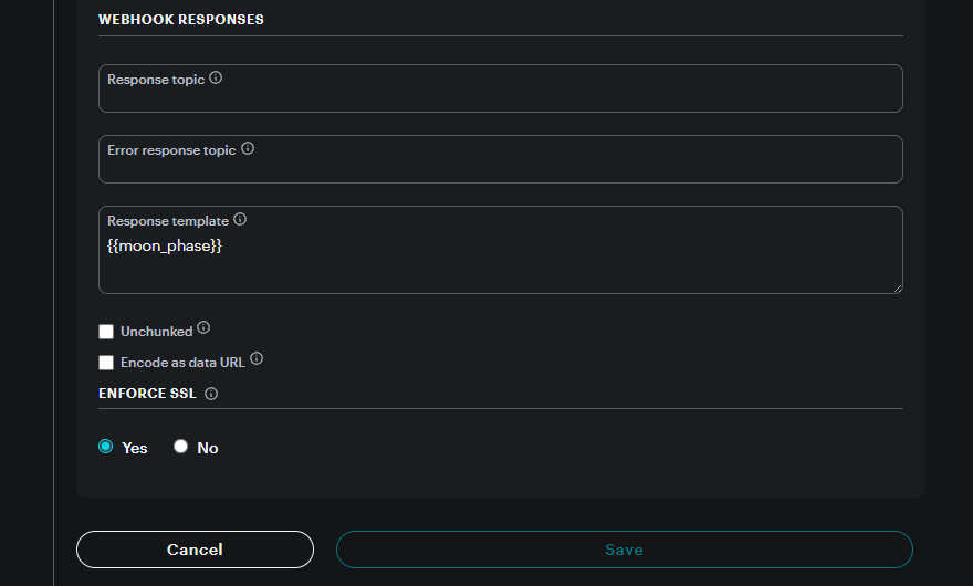
Since this response contains a lot of information, we’ll parse it down to just moon_phase.
Go to Extra Settings → Webhook Responses and add a response template:
{{moon_phase}}
Then hit Save. Your first webhook is ready!
2. Fetch current humidity and wind conditions
We’ll now create a webhook to fetch local wind and humidity data using OpenWeatherMap.
- Step 1: Create an account on openweathermap.org and obtain an API key.
- Step 2: Set up a new webhook with the following details:
Name: Get local wind and humidity forecast
Event name: get_wind
URL: https://api.openweathermap.org/data/2.5/weather?lat=37.87&lon=-122.53&appid=YOUR_API_KEY
Request Type: GET
Response template: {{main.humidity}},{{wind.speed}},{{wind.deg}}
3. Fetch sunrise and sunset times
We’ll use the free API from sunrise-sunset.org, which doesn’t require an API key.
Name: Get sunrise and sunset times
Event name: sunrise_sunset
URL: https://api.sunrise-sunset.org/json?lat=37.89&lng=-122.48
Request Type: GET
Response template: {{results.sunrise}},{{results.sunset}}
4. Fetch today’s weather forecast
While you can fetch day and night forecasts in one call, I find it easier to create separate webhooks. We’ll use the free API from weather.gov.
Name: Get day weather from weather.gov
Event name: get_day_weather
URL: https://api.weather.gov/gridpoints/MTR/82,111/forecast
Request Type: GET
Response template: {{properties.periods.0.name}}~{{properties.periods.0.temperature}}~{{properties.periods.0.shortForecast}}~{{properties.periods.1.temperature}}~{{properties.periods.2.temperature}}~{{properties.periods.2.shortForecast}}~{{properties.periods.3.temperature}}~{{properties.periods.4.temperature}}~{{properties.periods.4.shortForecast}}~{{properties.periods.5.temperature}}~{{properties.periods.6.temperature}}~{{properties.periods.6.shortForecast}}~{{properties.periods.7.temperature}}~
5. Fetch tonight’s weather forecast
Create another webhook for night forecasts:
Name: Get night weather from weather.gov
Event name: get_night_weather
URL: https://api.weather.gov/gridpoints/MTR/82,111/forecast
Request Type: GET
Response template: {{properties.periods.0.name}}~{{properties.periods.0.temperature}}~{{properties.periods.0.shortForecast}}~{{properties.periods.1.temperature}}~{{properties.periods.1.shortForecast}}~{{properties.periods.2.temperature}}~{{properties.periods.3.temperature}}~{{properties.periods.3.shortForecast}}~{{properties.periods.4.temperature}}~{{properties.periods.5.temperature}}~{{properties.periods.5.shortForecast}}~{{properties.periods.6.temperature}}~{{properties.periods.7.temperature}}~{{properties.periods.7.shortForecast}}~{{properties.periods.8.temperature}}~
With these five webhooks in place, your Photon 2 will be able to retrieve all the real-time data it needs.
Testing
If this is your first time working with the Particle platform, I strongly recommend starting with their documentation. Get familiar with the basics of Particle.publish and Particle.subscribe, and then experiment with Particle Webhooks. Once you have a solid understanding of these tools, move on to breadboarding the circuit. Start by setting up and testing just one webhook—say, the moon phase—before gradually enabling the others.
Resources
-
Adafruit GFX Library Guide
https://learn.adafruit.com/adafruit-gfx-graphics-library -
Volos Projects YouTube Channel
https://www.youtube.com/@VolosProjects -
TrueType to GFX Font Converter
https://rop.nl/truetype2gfx/ -
RGB565 Color Picker
https://rgbcolorpicker.com/565 -
Bitmap to C Array Converter
https://lcd-image-converter.riuson.com/en/about/
Help and Support
I’ve created a Discord server dedicated to Circuit Sculpture, and it’s grown to over 1,000 members! It’s the perfect place to ask questions, share your projects, or just hang out with others who love building circuit sculptures and electronics.
While I can’t respond to individual emails, posting your questions or ideas on the Discord channel is the best way to get my attention.
Join the community → Circuit Sculptures
If you found this documentation useful, please consider supporting me on Patreon or buying me coffee! Thank you!